Electric Circuits are an essential topic that cover the conservation of charge, the conservation of energy, the flow of current and the concept of voltage. In this CoolStuff article, I will describe in greater detail the concepts from the video and explain in greater detail the physics of each of the 9 experiments.
In the Coolstuff video, we demonstrate the fundamentals of electric circuits with this Investigating Electrical Circuits Kit which is more affordable and convenient than most pre-packaged kits for this purpose. The kit is designed to enable inquiry learning, that means that students will be able to do the experiments with almost no guidance from an instructor. Of course, it is helpful for you to be there to check the bulbs and batteries are functioning, but with just the circuit diagrams, a beginner should be able to build all of these set ups.
The kit comes with battery holders (which clip to each other easily), posts (which have excellent long posts for connecting wire leads), a switch (sometimes called a knife switch – but I don’t use this word in the classroom), lightbulb resistors, and connecting wires (10 long and 10 short wires). Also, you can add a Miniature Digital Ammeter and Miniature Digital Voltmeter (sold separately). These are very easy to connect because they have built in leads. Also, they have clear displays so that the reading of the meter does not interfere with student learning.
One of the best things about this kit is that the pieces magnetize to the mat, which is included. The mat itself is also a white board which you can use when guiding instruction, such as how to connect a voltmeter, how to connect an ammeter, or suggesting new circuit ideas. Teachers can walk from station to station and suggest a circuit group by group, or students can use the white board to make doodles of their own circuit ideas. The magnets stick very well, being neodymium, which is an added value. They help keep the circuit organized and prevent the pieces from sliding all around.
From here we provide several set ups that you might want to use and as you learn circuits for the first time. The first few set ups are simple circuits that demonstrate basic electrical concepts. Each following circuit is a step toward building more complex circuits and each has a lot to say about the physics of electricity.
1. Your first circuit:
This circuit is designed to show us that a circuit is a circle. That means that the flow of current is continuous and in a loop. A wire connects to a battery, to a light bulb, to another wire and back to the battery. This lights up the bulb, but not very bright. The current is allowed to flow in a circle.
Current is defined as the “imaginary flow of positive charge” – in this case – from the positive end of the battery to the negative end. However, as most people know, it is actually electrons that flow from the negative end to the positive end. It is very difficult to prove that it actually is electrons that flow (the first experiment was called “the Hall effect” and later cathode ray tubes provided more evidence).
The Intensity of Current Flow can be calculated as I = Q / t where I is intensity of current (amps), Q is quantity of charge (coulombs), and t is time in seconds.
Any break in this flow turns off the bulb, whether the positive end or the negative end of the battery. This is a 1.5V battery and the bulb is not very bright for only 1.5V.
It might seem like a trivial question, but it is quite a surprise to most students:
“What do you think will happen if I reverse the battery?” The light bulb still works as normal, it seems that lightbulbs do not know or care what direction the electric current flows.
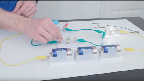
2. Batteries in Series:
Our next goal is to increase the number of batteries in the circuit. This will reveal the purpose of batteries. With the one battery the bulb is quite dim, but what will happen if we add another? The bulb is now glowing brighter, this demonstrates that applying more voltage gives more current. The logic of this is that batteries and the voltage they provide are the push that motivates the current. Sometimes voltage from a battery or generator is called “electro motive force.”
Now what if I add a third battery? Will that matter what direction I add the battery. If the battery is added backwards, it will cancel the forward pressure of one of the other batteries. So instead of being brighter, the bulb gets dimmer, when we set them all in the same direction the bulb will be much brighter. In this case we can add the voltages, 1.5V, 1.5V, 1.5V gives 4.5 volts. That is the rule for a series of batteries. The batteries are like pumps, that push the electric current. The harder they push, the more current can flow.
3. Batteries in Series:
Starting from a circuit of three batteries and one bulb we now choose to add a second bulb. But, what do you think this will look like? The result is that both bulbs light but slightly dimmer. The lightbulbs now are having to share the 4.5 volts provided by the batteries which gives 2.25 volts each. Lightbulbs in series use up the voltage evenly, so long as they are they same bulb.
It is easy to guess what will happen when we add a third light bulb. Now all of them will be just as dim as the first circuit we studied above. Each bulb is only getting one battery’s worth of voltage, so 1.5 volts each.
Because light bulbs slow down the current they are called resistors… they resist the flow. The law that explains this is called Ohm's law. I=V/R. The intensity of current increases with voltage in the numerator but decreases with resistance in the denominator. In this experiment we had plenty of voltage, 4.5 volts, but we also had plenty of resistance about 21 ohms of resistance and that balanced out, giving us a low intensity of current.
This is not the time to introduce the idea of ohms, and perform calculations. But it is a good time to discuss conceptually that the batteries push current and the lightbulbs resist it. Later, when we use the ammeter, it will be appropriate to make such claims of resistance being measured in ohms.
By the way, what is an ohm? You probably feel quite confident in volts, having handled batteries all your life, and you probably feel quite good about current watching it flow through these bulbs, but what would you call an ohm? Well, lets start with the original unit of Georg Ohm. He used, as his standard, 1000 feet of copper wire. That much copper does not slow down electricity very much because copper is such a great conductor. So it is only one ohm’s unit worth of resistance. Copper is the second best conductor, next to silver, and gold is third. Since copper is much less expensive that silver – and doesn’t corrode as quickly – we make almost all of our wires out of copper.
4. Your First Switch:
Going back to three batteries and one light bulb is a good idea for this lab. We want the throwing of a switch to be a big deal. By definition, a switch can be anything that connects a circuit, for example a button switch. But, the type of switch we are using is a “knife switch,” although I don’t call it that when I am teaching. We are going to add a switch near the batteries for emphasis, but it really can go anywhere.
A switch is a circuit breaker, that means it can interrupt the flow of current. Since everyone has used a switch before, it is a bit silly to define a what a switch is. When the open switch is added to the circuit, it does not initially light up. But when we close the switch, then metal touches metal and it does light up.
5. Light Bulbs in Parallel:
The idea of a parallel circuit must be treated with great care and not rushed. Although so far every aspect of building circuits has been straight forward and intuitive, the results of building a parallel circuit is always surprising. Why is this? Students do not understand the idea of pressure. Voltage, being analogous to pressure, is constant no matter how many paths of flow there is out of the battery.
Imagine a very large tank of water. If you poke a hole some where the water flows out because of the pressure, if you poke another hole somewhere else (same height), you can access the same pressure. It is possible to get lots of water flowing at once at this pressure with little affect on the total pressure. But you also know that this is coming at the expense of the total available water in the tank and that it will run dry faster. You don’t get something for nothing. With this analogy in mind a parallel circuit makes sense.
The arrangement of a parallel circuit means that the current is flowing in parallel paths – in this case through light bulbs. It is helpful to use the posts for these because they allow for multiple connections. I think it is best to have the bulb glowing brightly (3 batteries) to contrast with the series circuit. We start with just one bulb, glowing brightly, and add a second bulb for current to run parallel. What do you think will happen? It also glows brightly! But what about three bulbs connected in parallel? All three now glow bright!
Although it seems like we are getting free current, we are not. What we are getting is each light bulb being connected directly to the batteries. Each lightbulb gets all 4.5 volts from this set up. Because there is nothing resisting their connection to it. However, this type of parallel circuits uses more power from the batteries, this means that the battery will get used up faster, and go dead sooner.
6. The Split Circuit:
We now combine both parallel and series into one circuit. How will the bulbs be glowing in this circuit? Well, the current flows from the battery, and then it has to split for Bulb A and B, each getting half of the current. However, it does come back to together for bulb C. That means that bulb C must get all the current – twice as much as A or B and therefore it should be bright, this is indeed true.
The flow of current is like the flow of water. If it was water it would make perfect sense that 3 gallons could split into 1 ½ and 1 ½ but then come back together again for bulb C who gets all three. Notice that the brightness of bulb C is much greater than the brightness of bulb A or B. This means that bulb C must be getting more voltage as well, we have seen that brighter bulbs occur when there is greater voltage. This split circuit is a hint that parallel circuits reduce resistance and therefore require less voltage (energy per charge) compared to series circuits.
7. The Short Circuit:
Now that we have studied parallel circuits, we are ready for the idea of the short circuit. We start with this circuit, the three bulbs in series, and all the bulbs are glowing dimly. But this time we are going to put a wire across the middle bulb. What will happen?
The middle bulb goes out, completely! The other two bulbs both glow brighter. This must mean that most of the current flows through the wire. This is sometimes called a path of least resistance. It is easier for the flow of electric current to flow through the wire than a light bulb, which would resist the flow. Wires have very little resistance. This arrangement is called a short circuit – not because it is shorter – but because it is a short cut. Do you imagine that the current is going faster in the shorted circuit?
8. Using and Ammeter:
Electric current, being measured in amps, can be measured when the current is allowed to run through the Miniature Digital Ammeter. We normally add the ammeter in series with our circuit so that we can find out how many amps are flowing. 1 amp would be a huge amount of current (for example a bright 120W incandescent bulb uses 1 amp) and we can see that here with the three bulbs that the current is only .212 amps, but when we short the circuit, we get of course more, .257 amps. This proves that more current flows through a short circuit. I can also short both bulbs to show that for just one light bulb it is .355 amps. More still. In this write up I am using amps, although the meter usually expresses these in milliamps, 212mA for example.
This ammeter is much more convenient than traditional bulky or confusing ammeters that we all grew up on. You can see the appeal. It hooks up easily and the read out is clear. It is also smaller so that it does not crowd up your circuit arrangement.
Regarding calculations, you might be tempted to use ohms law to investigate the resistance of these light bulbs. You will find that they do not have a simple relationship of 7 + 7 + 7 ohms = 21 ohms. In fact, for the single bulb on its own, the resistance is 12 ohms, almost twice as much as the 7 ohms it had in series! This is because increasing temperature can increase resistance. In the case of the light bulbs that means that when they are bright they are hot and their resistance is higher.
9. Using a Voltmeter:
You can use the Miniature Digital Voltmeter to measures voltage. The way you can use it is to put it in parallel with anything you want to know how many volts it either is using or provides. This is called “the voltage drop across” the circuit element. For example, you can readily show that a battery is providing 1.5 volts just like I’ve been telling you. And two makes 3.0 volts, almost exactly. The light bulbs do indeed use up specific values of voltage and you can even use this voltmeter to see how many volts each light bulb is using no matter how complex your circuit.
Voltmeters have very high resistance, unlike ammeters which have very low resistance, therefore we cannot just insert them into the circuit like another light bulb. They are to be clipped across the circuit element you are probing.
From these experiments you now have the skills and vocabulary to understand more complex circuits. You can draw and create whatever you imagine. This kit makes a wonderful introduction to students so that they do not have to get stuck wiring confusing breadboards as they are struggling to learn. Breadboards have their place but they are not the path to knowledge for the beginner. This kit is built for students and that is what makes it cool.


